Introduction to link layer
- Network layer provides communcation service between any two hosts
- An Ip datagram may travel through multiple routers and links before it reach its destination
The path go to multiple routers from path to server
- Link layer sends datagram between adjacent nodes (host or routers) over a single link
- Ip datagrams are encapsulated in link layer frams for transmission
- Different link layer protocols may be use on different links
Different link protocols are use on different links
Possible Link layer Services
- Framing
- Encapsulate datagram into frame, adding header and trailer to the payload
- This becomes a frame
- Router will remove the header and trailer and add a new header and trailer
- Link access cotnrol
- When multiple nodes share a same single link, need to coordinate which nodes can send frames ar a certain point of time.
- Reliable delivery
- Seldom use on low bit error link(fiber)
- Error detection
- signla faults
- Signal noise
- Depends on the link layer protocols
- Error correction
- Receiver identifies and correct the bits
Link Layer implementation
- Link layer is implemented in adapter or on chip
- Adapters are semi autonomous, implementing both link and physical layers
Router only has up to 3 layers with the last layer being network, that is why router is consider a 3rd level device
- Transmission over the link is control by link layer protocol
Error Detection and Correction
- Popular error detection
- Checksum (TCP/UDP/IP)
- Parity Checking
- CRC (Link layer)
- It is not 100 percent relaible
- May miss some errors but rare
- Large error detection and correction fields yield better detection
CRC is slow if implemented in software thus it is better to be implemented in hardware not software
Parity Checks
Single bit parity
- Can detect single bit errors in data
- Select the parity bit such that the sum of the parity bit and the data is even
- e.g: if there are 9 ones in the data, we will choose a one in for parity bit so that it will be 10 in total (even)
- This only checks for one bit flip
- Receiver will miss the error if two bits swap
- This is only use for reliable link transfer as it is fast
Two dimensional bit parity
- Can detect correct single bit errors in data
- Compute the sum for every row and every columnn and find the parity bit for each row and column where it must be even
- This can be use to detect exactly which bit is flip and correct it (oNLY IF ONE BIT)
There is an higher overhead of bits that we need to sync (60 percent overhead). This is a tradeoff
Cyclic Redundancy Check (CRC)
- Powerful error detection coding that is widely use in practice
- D : Databits
- G: Generator of r + 1 bits agreed by sender and reciever
-
R: Will generate CRC of r bits
- Calculation is done in bit-wise XOR operation without carry or borrow
e.g r = 3
- Because r is 3, we will not remove the front 0
- Sender sends (D,R)
- Reciever knows G, divides (D,R) by G
- if non 0 remainder: error is detected
Multiple Access Links and Protocols
2 types of network links
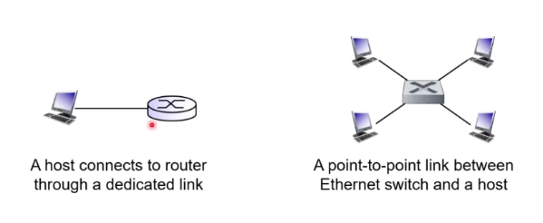
- Type 1: Point to point link
- Sender and receiver connected by a dedicated link
- Example protocols: Point to point protocol (PPP), Serial Line Internet Protocol (SLIP)
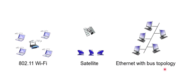
- Type 2: BroadCast Link (Shared medium)
- Multiple nodes connected to a shared broadcast
- When node transmit a frame, the channel broadcast the frame and each other node receives a copy
Multiple Access Protocols
In a broadcast cannel, if two or more nodes transmit at the same time
- Every node have mutliple frams at the same time
- Cause collision
- Multiple access Protocol is used
Multiple access protocols can be categorized into
- Channel partitioning
- Take turns
- Random access
Channel partitionaing protocols
TDMA (Time division multiple access)
Time is divided into different slots Each piece is further partition into slots This pattern is repeated. Each nodes get a fix lenght slot Unused slots go idle
- The first computer will get different slot
- Everyone willl get a few seconds to transmit
- This is similiar to CPU Scheduling > CS2106
FDMA (frequency division multiple access)
- Channel specturm divided into frequency bands
- Each node is assign a fixed band
- Unused transmission time in freq band go idel
- Every node is guranteed to use
FDMA is used in radio signals where the receiver will filter and tune into that frequency and extract the band
Taking Turns protocols
Polling: Master node invites slave nodes to transmition in turn Every node has a chance to sent.
We will not waste time to ask slaves that have no data to be transmitted. This is more efficient
Good
- Fair protocol
- Efficient compared to division
Bad
- There is an overhead for polling
- Single point of failure (Master node)
Token passing: Control token is pass from one node to another sequentially
It is only use for the token. Only the host with the token is allow to send data. Token is pass after one another. The nodes is usually organise in a ring.
Good
- No collisions
Bad
- Token overhead to pass
- Single point of failure (token)
Random access protocols
When node has a packet to send
- A no priority coordination among nodes
- This might cause colllions (Two or most host are sending at the same time and it might collide)
RAP will specify:
- Detect collision
- Recover
Slotted ALOHA
Assumptions:
- All frames are of equal size
- Time is divided into slots of equal length (length = time to transmit 1 frame)
- Nodes starts to transmit only at the beginning of a slot
Operations:
- List to channel while transmitting (Detect)
- If collision: Node retransmits a frame in each subsequent slot with probability p until success
- p is design to respond to network congestion where a smaller p is chosen if there is a network congestion
Good
- Simple to understand
Bad
- Wasting some of the channel capacity
- Need synchronisation
- best case is 30 percent use of channel capacity
If you have a large bandwidth, it is useless because we are only use 30 percent
Pure (Unslotted) ALOHA
Even simpler: No slots and no synchronisation
- When a node has a frame to send, it just transmit
- Chance of collision then increase:
- Frame sent at t0 collides with other frames send in t0-1 and t0 +1
The front frame may overlap with the next node
- Channel utitlization is worst here (15 percent)
Carrier Sense Multiple Access
CSMA sense the channel before transmission
- Idle: Transmit
- Busy: Defer transmission
Human analogy: “Do not interrupt others”
But will collision still happen?
Yes, if two nodes sense simultanously and found idle, they will transmit at the same time.
- Propagation delay: Two nodes may not hear each other transmission delay
When a node is at the far end of the transmission channel, that node may not know whether the other nodes is sending something.
The protocol is not very smart, even thou there is a collision, it still continue to finish and retransmit
CSMA/DA (collision Detection)
Transmission is aborted quickly as soon as collision is detect
- Retransmit after a random amount of time
This is the underlying method of ethernet
Minimum Frame Size
- What if the frame size is too small to be able to be detected that it collided
- This leads to no retransmssion
This is why there is a certain limit to the frame size to ensure that CSMA/DA collision can be detected (Ethernet = 64 bytes min)
CSMA/CA (Collision Avoidance)
Collision detect is easy in wired LAN but difficult in wireless
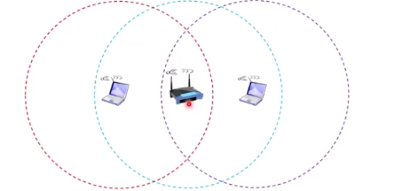
A signal has a fixed range which can only be detected if within that range. Outside that range, it will become weaker.

802.11 (WIFI) use CSMA/CS Protocol instead, receiver needs to return ACK if a frame is recieved OK.
Mac Address
Every adapter has a mac address (Physical or LAN address)
- Used to send and recieve link layer frames
Every network interface card has a mac address
- Mac address is used to send frames and check if the destination mac address of the frame matches its own
Mac address is 48 bits and is hardcoded in the ROM. This address is set by IEEE.
IP address vs MAC address
- 32 bits - 48 bits
- Network layer - Link layer address
- Datagrams - Frames
- Src to dest - Over every single link
- Dynamic assign - Permanent
They follow a hierachical way of asking for packets. This is done by looking at the prefix rather than the entire 32 bits in order to check if the packet belongs to them
** How do we know tha MAC address of a recieving host knowing its IP?**
Use ARP
Each node (router or host) has an ARP table which stores:
- Ip address
- Mac address
- TTL
A host can have 3 address, the ip address, the host name and the MAC
The overall system is optimised to work fast. The ARP table only save the mappings of your neighbours
Sending frame in the same subnet
A want to send to B in same subnet
- If A knows B mac address
- Create a frame with B mac address and send it
- Only B will process the frame
- Other nodes may receive but will ignore this frame
- What if A does not know the B’s Mac address
- Broadcast a query packet containing B’s IP address and destination MAC address is set to FF-FF-FF-FF-FF-FF
- All the other nodes in the subnet will received but only B will reply to it
- B will send a reply frame that is sent to A’s Mac address
- A caches B’s Ip to Mac Address mapping in its ARP table until ttl expires
** How to know if A and B are in the same subnet**
Calculate using the IP address and prefix given by B and compared it with A to see if the subnet is the same.
Sending frame to another subnet
What if A and B are different subnet?
- A should create a link layer frame with the router’s Mac address and B’s ip add the address destination
-
Router would see that the ip address is different from it even thou the mac is matching.
-
It will look into its forwarding tables and decide how to forward.
-
It will construct a new frame with a new destination mac address and send to subnet 2
If it is a pc, it will drop
Switch Local Area Networks
Lan
That interconnects computer within a geographical area such as office building or university campus
- Consist of multiple subnet
Lan technologies:
- IBM token ring
- Ethernet
- Wifi
- Others
Eternet
- Dominant wired LAN technology
- simpler and cheaper than token ring and ATM (asyncronous transfer mode)
Eternet Standards
- Different speeds
- Different physical layer media: Cable, fibre optics
- Mac protocol and frame format remains unchanged
Standardize the protocol and the frame format.
- Twisted pair copper connectors
- RJ45
- CAT 6
- Optical fiber connectors
- LC/PC connectors
- SC/PC connectors
- Single mode fibre
Copper has a problem where it is easily affected by electrical noise
Physical topology
-
Bus: All nodes can collide with each other
-
Star: Switch in the center and nodes do not collide with each other
Star is more commonly used because switch has become cheaper and are still fast. There is also less collision compared to bus topology.
Eternet Frame structure
- Sending NIC adapter encapsulte IP datagram in ethernet frame
- Preamble:
- 7 bytes with pattern 10101010 follow by 1 byte with pattern 10101011
- Use to synchronise reciever and sender clock rates
- Provides a square wave pattern that tell the reciever the sender’s clock rate
-
Tells reciever the width of bit
- Source and destination Mac address
- If NIC recieve frame with matching dest/broadcast address, it pass the frame to network layer (ie accepts)
- Else it discards
- Type: Indicates higher layer protocol
- CRC: Corrupted frame will be droped
Eternet data delivery service
- No handshaking between sending and recieving
- Unreliable: The receiving NIC does not send the ACK or NAK to sending NIC
Collisions in BUS typology Ethernet
Ethernet CSMA/CD
- NIC recieves datagram and creates a frame
- If channel idle, start frame trans, else waits till channel idle then transmit
- If NIC transmit entire frame without detecting another transmission, it is done
- Otherwise, it aborts and send a jam signal
this jam signal is to make sure the other nodes know that there is a collision
- After aborting, NIC enters a binary back-off
- after mth collision, NIC chooses K at random form
- NIC waits K*512 bit times before returning to step 2
Expontential backoff:
- After 1st collision, choose K from {0,1}; wait k* 512 bit transmission times before transmission
-
After 2nd collision, choose K from {0,1,3} …
- After Mth collision, choose K at random from {0,1,..2^m-1}
This is like a congestion control and eventually we will be able to push the message through but the throughput will decrese
- Goal: Adapt rtransmission attepts to estimate current load
- More collisions implies heavier load
- Longer back-off interval with more collisions
Ethernet switch
A link layer device use in LAN
- Store and forward ethernet frames
- Examines incoming frames’s mac address and selectively forward frames to one or more outgoing links
It is transparent to host
- Has no IP address
- Host are unaware of the presense of switches
If a host sends a packet to another host, the switch upon recieving will check the IP/MAc and forward it accordingly
- Switches buffer frames and is full duplex (It can send frames to each other simultanously at full speed)
How does switch know A is reachable via interface 1 and B is reachable via interface 4?
The switch stores the infomation in a switch table which contains:
- Mac address
- Interface to reach host
- TTL Using this, it is able to identify where to forward the packet
Switch: Self-learning
Switch learns which host can be reached through which interface
- when reciving a frame from A, note down the location of A in switch table
- If dest B is found in table, it will loopup and send
- If dest B is unknown, broadcast the frame to all outgoing links
This is inefficient though if we always use broadcast, this will cause alot of traffic
Interconnecting switches
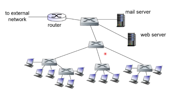
Switches can be connected in hierarchy
Switches will run out of ports thus we can use a spanning tree in which we use multiple switches.
There might be a case where we create a loop accidentally in a spanning tree, thus we must ensure we avoid the loop.
Switches vs Routers
Router is layer 3 while switch is layer 2 Routers understand both MAC and IP while switches only understand MAC
Switches are plug and play


